Manual Camera Calibration
This section describes the functions for manual camera calibration capabilities in TeleSculptor (TS) and steps to achieve, possibly correct, and export a camera calibration model.
Preparation
TeleSculptor can work with ffmpeg-readable videos (e.g. mpg, mp4, avi) or with image sequences. The latter can be specified by listing paths to individual images in a plain text file (e.g. images.txt) using one line per path/to/image/file. Standard image formats (e.g. bmp, png, jpg) are supported.
TeleSculptor has a capability to import PLY mesh or point cloud files via → → . Point clouds are imported as faceless meshes. The imported mesh is used as a 3D target for calibration. RGB[A] color space is currently supported. The alpha channel can be used to set mesh transparency levels.
We recommend geo-registering the mesh before importing it into TS to have the output calibrated camera parameters in mesh metric units and also automatically geo-registered with the 3D model.
Calibration
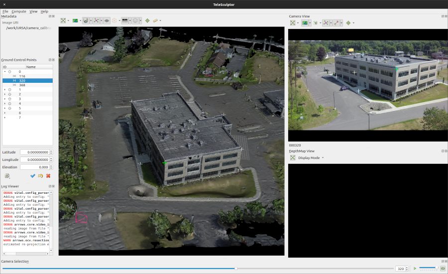
Start the TeleSculptor GUI and proceed with the following steps in a new or an existing project.
New project
Create a new project using → (Ctrl+N) and select a folder for the new project, creating one if necessary. The project .ini file name will have the same name by default.
Select a video or image sequence text file using → → (Ctrl+O, I). Opening a large videos will initiate a potentially long search for metadata, which may be canceled via the menu action → .
Select a PLY file with a mesh or a point cloud using → → (Ctrl+O, M). The loaded 3D geometry should appear in the 3D world view.
Locate the desired video frame or image using the scrubber or spin box in the Camera Selection pane. Rotate the model in the world view as needed so the desired point correspondences are visible.
Select ![]() Edit Ground Control Points (in the world view)
to activate editing mode for ground control points in the world view.
Place points using Ctrl+Click.
Telesculptor attempts to place points “on” the loaded mesh,
but it may be helpful to rotating the world view
to verify that points are placed in the right 3D location.
While editing, points may be dragged as needed.
Newly placed points will appear in the Ground Control Points list,
and may be given names if desired.
Edit Ground Control Points (in the world view)
to activate editing mode for ground control points in the world view.
Place points using Ctrl+Click.
Telesculptor attempts to place points “on” the loaded mesh,
but it may be helpful to rotating the world view
to verify that points are placed in the right 3D location.
While editing, points may be dragged as needed.
Newly placed points will appear in the Ground Control Points list,
and may be given names if desired.
To create 3D-to-2D point correspondences,
select ![]() Edit Registration Points (in the camera view).
Ensure that the desired 3D point is selected in the Ground Control Points list
(the selected point is highlighted in a different color).
Place a corresponding point using Ctrl+Left Click,
positioned to match the location in the camera image
to which the 3D ground control point would be projected.
The Ground Control Points list will show a glyph (
Edit Registration Points (in the camera view).
Ensure that the desired 3D point is selected in the Ground Control Points list
(the selected point is highlighted in a different color).
Place a corresponding point using Ctrl+Left Click,
positioned to match the location in the camera image
to which the 3D ground control point would be projected.
The Ground Control Points list will show a glyph ( )
to indicate that the point has a corresponding camera registration point
associated with the active video frame or image.
Once created, points may be dragged as needed
to fine tune their locations.
Select another 3D ground control point and repeat
until at least six correspondences have been created
for the active video frame or image.
The relevant edit mode actions may be used at any time
to switch between editing points in the camera or world views.
)
to indicate that the point has a corresponding camera registration point
associated with the active video frame or image.
Once created, points may be dragged as needed
to fine tune their locations.
Select another 3D ground control point and repeat
until at least six correspondences have been created
for the active video frame or image.
The relevant edit mode actions may be used at any time
to switch between editing points in the camera or world views.
Once six or more correspondences have been defined,
the camera model calibration process may be invoked
from the action located in the drop-down
associated with ![]() Edit Registration Points.
Check the Log Viewer for the re-projection error
or for any error messages (e.g. insufficient calibration points).
Upon successful calibration,
the world view will show the projected camera image
(if
Edit Registration Points.
Check the Log Viewer for the re-projection error
or for any error messages (e.g. insufficient calibration points).
Upon successful calibration,
the world view will show the projected camera image
(if ![]() Show Camera Frame Image is enabled),
and the camera view will show the ground control points
projected onto the camera image.
Show Camera Frame Image is enabled),
and the camera view will show the ground control points
projected onto the camera image.
Repeat this process on additional frames. Point locations may be adjusted as needed, as described above, to refine the camera model calibration. Camera calibrations may be refined at any time; it is not necessary to “finalize” one camera model before calibrating additional camera models.
When satisfied, → → may be used to save the parameters of all calibrated cameras to KRTD text files. Each file will capture the intrinsic matrix K, the rotation matrix, the translation vector and the lens Distortion parameters.
→ → will export all of the ground control points and their corresponding camera registration points as a GeoJSON-like file. (Only the geodetic locations, if available, conform to GeoJSON; the world and camera locations are stored as extensions.) This will output all points, whether or not calibration was performed successfully.
Existing project
Open an existing project using → (Ctrl+O, P). The project’s corresponding video or image sequence, and the 3D mesh or point cloud, will be loaded automatically. Follow the calibration procedure described for new projects, above.